
How to Overcome Challenges in Manufacturing Thin-Wall CNC Parts?
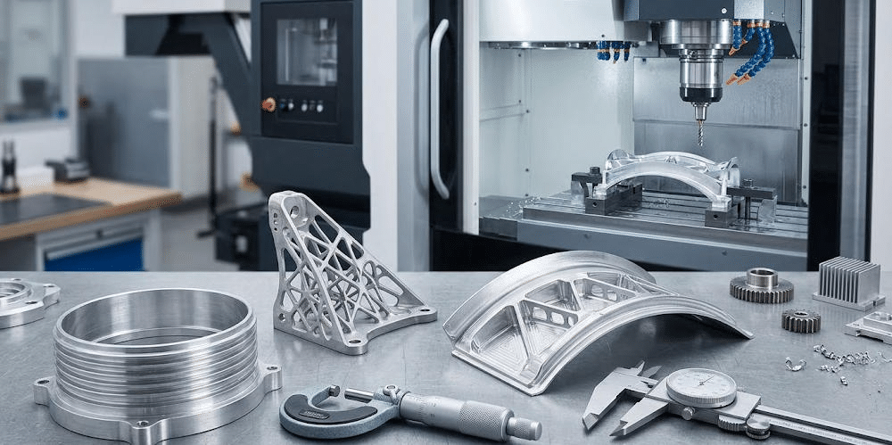
Thin-wall CNC parts are common where weight matters and details must stay accurate with efficient material utilization, such as aerospace, automotive, medical devices, electronics, and industrial machines. In these CNC machined parts, the walls are kept thin, but the dimensional accuracy and mechanical performance needed for the job are still maintained.
However, manufacturing thin-wall CNC parts is more challenging than machining thicker parts. The walls have low stiffness, so they can shake during cutting. They may warp, show leftover stress, and end up with size errors. Small shifts in cutting force, heat level, or how tightly the part is clamped can change the final result.
For manufacturers, it helps to know these challenges early. That knowledge supports better machining planning, smoother output, and steady part quality. In practice, manufacturers produce thin-wall CNC parts with greater precision and reliability by optimizing material choice, cutting parameters, tool paths, workholding, and inspection procedures during and after machining.
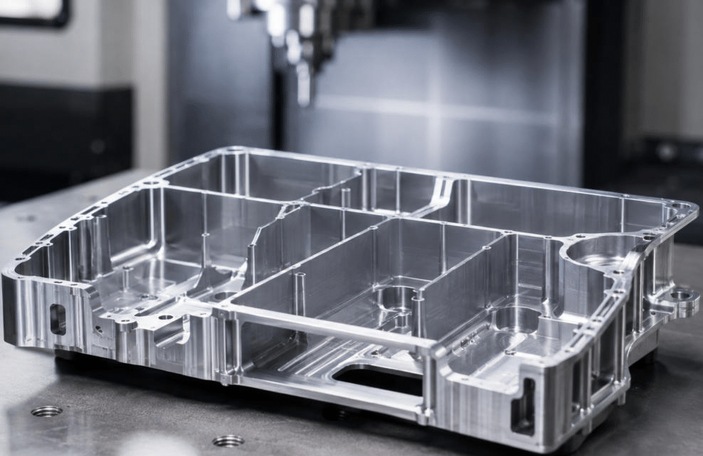
Table of Contents
Understanding Thin-wall CNC Parts
Thin-wall CNC parts are precision pieces where the wall thickness is small compared with the overall size. Most are made with CNC milling, CNC turning, or other cutting-based processes.
Compared with thick parts, thin-wall shapes resist load poorly. Small forces from the tool can lead to vibration, bending, or shifts in dimensions. So the shop needs focused methods and tight control of the process.
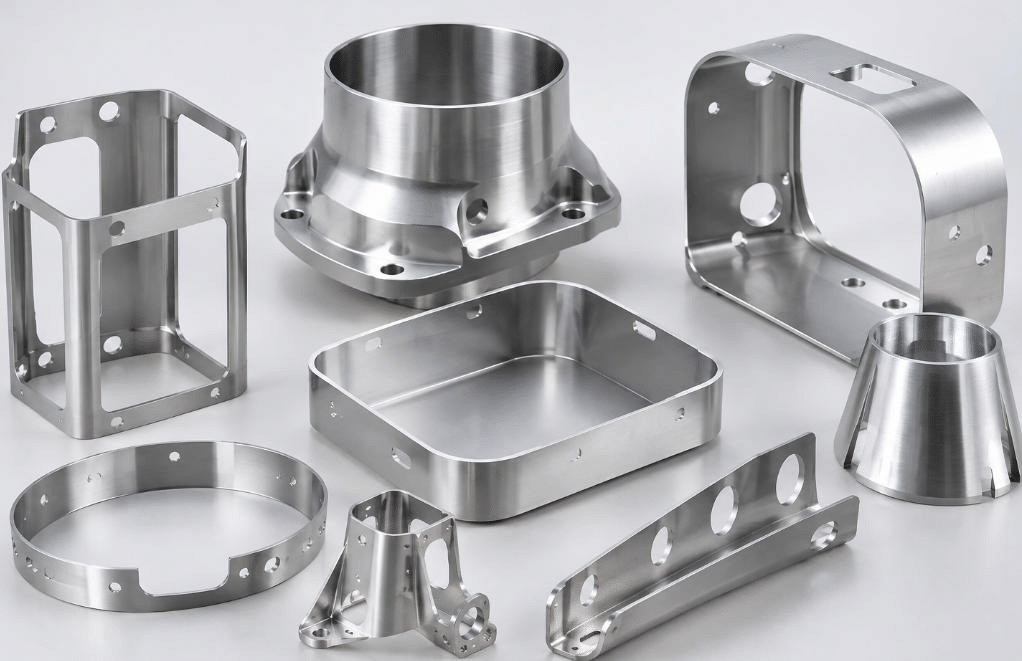
You can see these parts in aerospace brackets, light housings, electronic enclosures, medical instrument parts, and thin-walled aluminum parts.
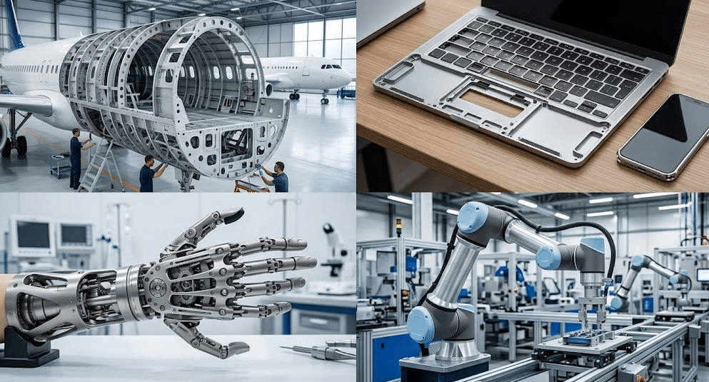
Wall thickness is not a fixed rule. It depends on the material, the geometry, the part size, the machining method, and what the part must do in service. Different designs call for different thickness levels.
Common Challenges and Solutions in Manufacturing Thin-Wall CNC Parts
1. Material Deformation During Machining
Material deformation is a frequent issue in thin-wall CNC work. Thick solids hold shape better, but thin walls can bend or flex when the cutter loads them.
During milling or turning, the tool pushes on the workpiece. If the wall cannot resist that push, it can pull away from the tool. Then you can get uneven wall thickness, size mismatches, a weaker surface finish, and trouble hitting the required tolerances.
This gets worse with materials that flex more, like many aluminum alloys. It also gets worse with complex shapes or areas that are not well supported.
Solution
To reduce deformation, manufacturers can lower cutting forces. They can do this by picking the right tools, tuning feed rates and cutting depth, and using machining plans that spread material removal more evenly. Fixtures can help too. So can temporary support pieces. A careful machining order can also support the workpiece, so it stays steady during production.
2. Tool Vibration and Chatter
Tool vibration and chatter often show up in thin-wall CNC work. Thin walls do not resist force well. They can shake when the tool enters a cut, mainly if the tool is working over a long unsupported area.
Chatter can hurt the finish. It can also damage dimensional accuracy. Tool life may drop. Machining can slow down. In bad cases, the part may show clear vibration marks. The cut can also become unstable.
Chatter usually comes from several sources. These include too much tool overhang. Spindle speed that is not a good match can also trigger it. Weak workpiece support plays a role as well. Worn cutting tools add to the risk. Tool shape and cutting settings that do not fit together can also lead to chatter.
Solution
Manufacturers can reduce vibration with more rigid cutting tools. They can cut down on tool overhang. Spindle speed and feed rate should be tuned to a stable region. Tool path choices matter too. Adaptive machining can help. Dynamic analysis can point to stable cutting conditions. For very flexible parts, changing the machining sequence can help preserve stiffness in the first steps. That can lower vibration early in the process.
3. Residual Stress and Part Distortion
Residual stress is another key problem in thin-wall CNC part work. These hidden stresses can come from how the base material was made. They can also come from heat treatment. Previous machining steps can add stress too. Uneven removal during past operations can also contribute.
As material is cut away, the stress pattern shifts. Then the remaining thin-wall structure may bend, twist, or warp. This can happen during machining. It can also happen after the part comes off the fixture.
This issue is common in aerospace parts and other high-precision work. These parts often need tight tolerances. A part might look fine while it is clamped. After the fixture is removed, distortion may appear.
Solution
To address this issue, manufacturers should consider material stress-relief treatments when appropriate, balanced material removal, and staged machining operations. Rough machining can be followed by a stress-relief process where suitable, then semi-finishing and finishing operations. Measuring the component at intermediate stages also helps identify distortion before the final machining process is completed.
4. Maintaining Dimensional Accuracy and Tight Tolerances
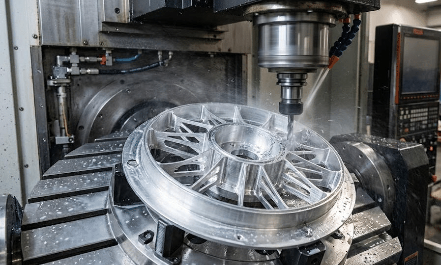
Thin-wall CNC components usually have tight tolerances on wall thickness, flatness, parallel alignment, shape accuracy, and general form. Hitting all of that is not easy. Thin parts flex with cutting load, expand from heat, change with tool wear, and can distort under clamping force.
Small changes can cause fit issues later. They can also weaken the finished structure or fail the quality check. The task gets harder with many thin walls in one part, narrow pockets, curved faces, and detailed internal shapes.
Solution
To achieve tight tolerances for thin-wall CNC parts, control has to cover the whole production flow. Use CNC systems that match the job. Rely on measurement tools that are checked and tuned. Keep the workholding stable. Set cutting settings that suit the material. Tool wear compensation can help too, and in-process checks can reduce drifting dimensions.
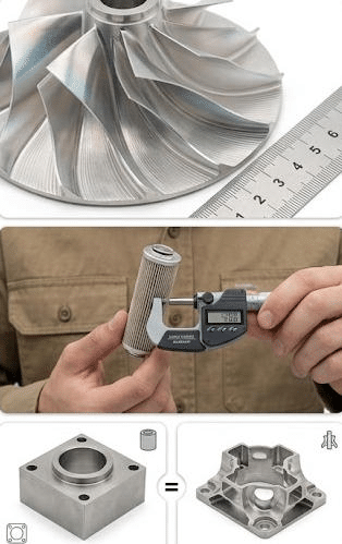
For parts that must meet high precision, use a CMM, a laser measurement system, or other metrology tools to confirm key dimensions. Choose a checking approach that considers part flexibility. If the inspection fixtures press too hard, they can bend the part and skew the results.
5. Heat Generation and Thermal Effects
Heat generated during CNC machining can significantly affect thin-wall components. Cutting friction, tool-workpiece contact, and chip formation introduce heat into the machining zone. Because thin walls have limited thermal mass, local temperature changes may cause relatively rapid expansion and contraction.
These thermal effects can lead to dimensional errors during machining. Once the component cools to the inspection or operating temperature, its dimensions may differ from those measured immediately after cutting.
Excessive heat can also accelerate tool wear, affect surface integrity, and contribute to unstable machining conditions. Materials with low thermal conductivity or difficult machining characteristics may require additional attention to heat management.
Solution
Manufacturers can reduce thermal problems by selecting appropriate cutting speeds, using sharp tools, applying suitable coolant or lubrication strategies, and ensuring effective chip evacuation. Allowing sufficient time for temperature stabilization before final inspection can also improve measurement reliability.
6. Workholding and Fixturing Difficulties
Good fixture support is required for thin-wall CNC work. Still, it is hard to find the right clamp force. You want the part held firmly, but you do not want it bent.
If clamping is too tight, the thin wall can warp or get crushed. If the part is not held enough, it can shift or shake. That can lead to dimension misses and a rougher surface.
Conventional clamping setups might not hold well on parts that have odd outlines, big internal voids, or several narrow sections. With these cases, some makers switch to made-to-fit fixtures or use a different holding approach.
Vacuum-style fixtures, soft jaw inserts, flexible support blocks, and special locating points can spread the grip load more evenly. The best choice depends on the part material, the shape, the cutting loads, and the number of units planned.
Solution
A good fixture needs solid stiffness, but it must still leave room for the machining areas that matter. When possible, it is also smart to think about how the part will act after the clamp is released.
7. Tool Selection and Tool Wear
Picking the right tool matters a lot for thin-wall CNC parts. If the tool makes high cutting forces or does not move chips out well, you can see chatter, bend or flex, and poor surface results.
Many factors steer the outcome. Tool shape, how sharp the cutting edge is, coating type, tool size, flute design, and the tool holder stiffness all play a role. For instance, sharp tools with the right rake angles can cut forces in some materials. But a very long, thin tool can lead to more vibration.
Wear also adds variation. When the cutting edge wears down, forces and heat can rise. That makes it harder to keep dimensions steady and hold surface finish targets.
Solution
Manufacturers should match tools to the workpiece material and the feature form. They should also track tool life and swap tools once wear starts to harm quality. Tool paths should be planned to limit unnecessary contact and avoid sudden load jumps.
8. Complex Tool Paths and Machining Sequences
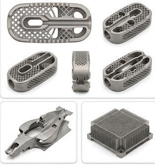
Thin-wall parts often include tough shapes such as pockets, ribs, rounded areas, and irregular wall thickness. The machining order can change how stiff the remaining part stays during work.
If too much material is removed early, the part may lose strength and later steps can become harder. Also, cutting one side more than the other can create uneven stress and raise the chance of part distortion.
A solid machining sequence should keep structure stiffness as high as possible at the start. Plan roughing, semi-finishing, and finishing so material removal and dimensional control stay balanced.
Solution
Manufacturers may also use adaptive CNC tool paths, smaller step-downs, staged pocket machining, and optimized cutting directions to control cutting forces. In complex projects, CAM simulation can help identify potential tool collisions, excessive engagement, and unfavorable machining sequences before production begins.
9. Surface Finish and Edge Quality
Making a smooth surface on thin-wall parts during machining is not always easy. The workpiece can shake. The tool can flex. Built-up edge can form. Cutting forces can run too high. Feeds that are not right can also lead to rough spots on the surface.
Thin walls and sharp edges may also burr up. They can tear in small areas. They can get nicked when parts are deburred or handled. If these issues show up, assembly can suffer, fatigue life can drop, the look can worsen, and function may not stay reliable.
Manufacturers should tune finishing settings, keep cutting edges in good shape, and pick tool shapes that fit the work material. Tool routes need steady contact with the cut. Deburring steps should match the wall thickness and the edge needs.
Solution
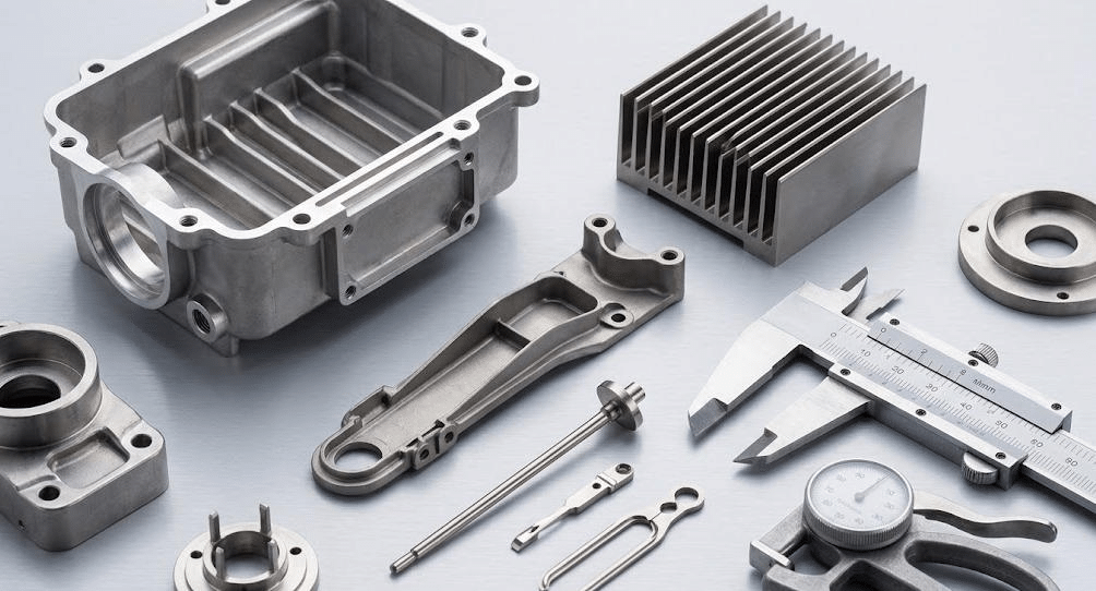
Inspecting CNC part surface finishing should cover what you can see and what the part must do. For some uses, more measurements are needed. That can include surface roughness, edge condition, and how well key features hold up.
10. Production Cost and Manufacturing Efficiency
Thin-wall CNC machining can cost more than machining thicker, more typical parts. It often means slower cutting, smaller cut depth, special clamps or fixtures, and extra checks before the parts are accepted.
Scrap and rework risks rise too, especially when a part can warp or shift in size. If a part fails inspection late in the run, the loss is not minor. It can waste stock, spindle time, machine hours, and operator effort.
So the shop has to trade speed against stable process results. Just raising the cutting speed may not boost output. It can also raise vibration, speed up tool wear, and increase the chance of rejection.
Solution
Cost control starts with reviews for how the part is made. It also uses the right material choice, well-planned tool paths, and tolerances that make sense for the job. Using proven machining settings, keeping track of tool wear, and doing checks while the part is still in production can cut waste and help the output stay steady.
Best Practices for Overcoming Challenges in Manufacturing Thin-Wall CNC Parts
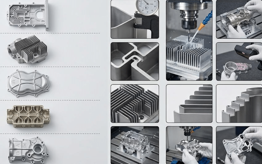
The most effective approach is to manage thin-wall CNC machining as an integrated process rather than treating each defect independently.
| Manufacturing Challenge | Best Practice | Implementation Method | Expected Benefits |
| Material Deformation | Reduce Cutting Forces | Use smaller cutting depths, optimized feed rates, and sharp cutting tools | Minimizes wall deflection and improves dimensional accuracy |
| Tool Vibration and Chatter | Optimize Machining Parameters | Adjust spindle speed, tool engagement, and tool overhang | Improves surface finish and machining stability |
| Residual Stress | Apply Staged Machining | Combine roughing, stress relief when appropriate, and finishing operations | Reduces warping and dimensional distortion |
| Tight Tolerances | Strengthen Quality Control | Use in-process measurement, calibrated instruments, and CMM inspection | Ensures consistent dimensions and specification compliance |
| Thermal Deformation | Control Heat Generation | Optimize cutting speeds, coolant application, and chip evacuation | Reduces thermal errors and improves surface integrity |
| Workholding Difficulties | Design Specialized Fixtures | Use soft jaws, vacuum fixtures, or conformal supports where suitable | Provides stable positioning while minimizing clamping deformation |
| Tool Wear | Select Suitable Cutting Tools | Match tool geometry and material to the workpiece and monitor tool life | Maintains machining accuracy and reduces tool-related defects |
| Complex Geometries | Optimize Tool Paths and Machining Sequences | Use CAM simulation, balanced material removal, and staged cutting | Improves machining efficiency and reduces distortion risks |
| Poor Surface Finish | Optimize Finishing Operations | Use suitable finishing passes, sharp tools, and appropriate feed rates | Produces smoother surfaces and reduces burrs |
| High Manufacturing Costs | Improve Process Planning | Apply design-for-manufacturability reviews, reduce scrap, and standardize proven parameters | Lowers rework costs and improves productivity |
| Inconsistent Wall Thickness | Monitor Material Removal | Use appropriate tool compensation and inspect critical wall sections during machining | Improves wall-thickness consistency |
| Low Production Yield | Implement Process Monitoring | Track machining parameters, tool condition, and inspection results | Identifies problems early and increases production reliability |
Successful thin-wall CNC machining depends on balancing precision, structural stability, and production efficiency. By combining optimized cutting parameters, specialized workholding, controlled material removal, and rigorous inspection.
Summary
Manufacturing thin-wall CNC parts requires precise control over machining forces, thermal conditions, workholding, tool selection, and material removal. Because these parts do not have much stiffness, they are prone to bend, chatter, heat stress, leftover stresses, and dimensional inaccuracies.
To overcome these challenges, you need a mix of good engineering choices and smart machining plans. You also need equipment that behaves well and a quality system you can trust. If the workpiece stays rigid, heat is controlled, material removal is balanced, and dimensions are checked through the full run, then manufacturers can raise accuracy, improve consistency, and lower the real total cost of thin-wall CNC machining.
For businesses seeking a reliable CNC parts manufacturer, check more than the machining equipment they have. Look at how much they have worked on thin-wall geometries. Also ask about their skills in making solid fixtures, improving the steps in the process, and doing careful measurement checks. A strong manufacturer can turn tough thin-wall drawings into high-quality custom CNC parts that fit tight specs and work well under demanding performance requirements.