
CNC Machining Surface Roughness: Guide to Ra and Rz Parameters
In CNC machining and precision manufacturing, surface roughness (surface finish) is one of the critical metrics used to evaluate the quality of machined parts. Whether for aerospace components, medical devices, or high-performance automotive transmission parts, a superior surface finish not only enhances visual aesthetics but also directly dictates wear resistance, sealing performance, fatigue strength, and fitting accuracy.
This article introduces the fundamental concepts, common parameters, typical machining processes, measurement techniques, and best practices for selecting and specifying surface quality requirements for precision CNC machined parts.
Table of Contents
What is Surface Roughness?
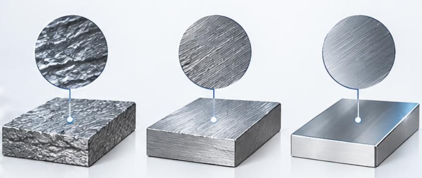
Surface roughness can be defined as the micro geometrical features having small distances and tiny peaks and valleys in the processed surface. To put it in simpler words, the surface of the material that looks smooth to the naked eye has some “highs” and “lows” under observation with a microscope or a surface tester.
There is micro texture development on the surface of the material due to friction, chipping, vibration, and heating during CNC turning, CNC milling, and CNC drilling operations.
Core Parameters Demystified: Ra vs. Rz
When specifying surface roughness on engineering drawings, Ra and Rz are the two most commonly used parameters. They convey the surface micro-geometry from the perspectives of “overall average” and “extreme peaks and valleys,” respectively:
1. Ra (Roughness Average – Arithmetical Mean Deviation of the Profile)
Definition: The arithmetical mean of the absolute values of the profile deviations from the mean line within the sampling length. In short, it represents the overall average height of surface irregularities.
Key Characteristics:
High Stability: Due to its being the most commonly adopted roughness parameter in the world, its averaging procedure makes sure that any sudden spikes or extreme burrs will not affect the value of the Ra significantly.
Applications: Suitable for general mechanical mating surfaces, structural cosmetic parts, and overall quality assessment of general machining.
Common Units: Micrometers (μm) or microinches (μin/ μinches).
2. Rz (Maximum Height of Profile)
Definition: The vertical distance between the highest peak and the lowest valley within the sampling length.
Key Characteristics:
High Sensitivity: Rz accurately detects occasional extreme surface defects such as tool marks, blowholes, tearing, or sharp burrs.
Applications: Frequently used in high-precision and critical scenarios requiring strict pneumatic/hydraulic sealing, high fatigue strength, or lubrication oil film retention (e.g., high-pressure valve bodies, engine cylinder blocks).
Rule of Thumb for Conversion: In practical engineering, for conventional cutting or grinding surfaces, the Rz value is typically about 4 to 7 times that of Ra (depending on the machining process and tool condition).
CNC Surface Roughness Chart
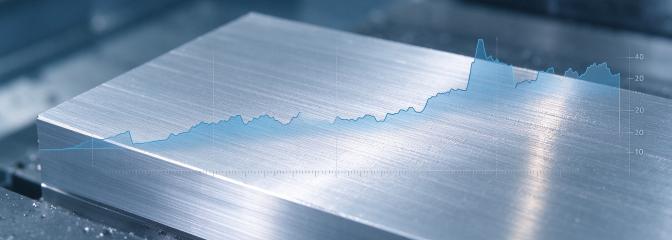
Various types of CNC machining operations and post-processing operations can obtain different surface roughness values. The following table shows standard Ra values and examples of their typical applications from roughing to super-precision mirror polishing:
| Process | Typical Ra (μm) | Typical Ra (μin) | Surface Characteristics & Typical Applications |
| Roughing / Flame Cutting | 12.5 – 50.0 | 500 – 2000 | Rough, visible tearing marks and tool residues; suitable for non-mating surfaces, large structural raw blanks, and fast material removal on non-critical areas. |
| Rough Milling / Turning | 6.3 – 12.5 | 250 – 500 | Visible tool marks and feed lines; suitable for non-mating surfaces of general structural parts, bases, and internal frame connectors. |
| Semi-Finish Machining | 3.2 – 6.3 | 125 – 250 | Minor visible tool marks, slightly rough to the touch; suitable for general mechanical structures, standard bolt clearance faces, and non-critical mating faces. |
| Standard Finish CNC | 1.6 – 3.2 | 63 – 125 | Industry-standard regular CNC machined finish; slight tactile damping, widely used for general mechanical mating surfaces, housings, and brackets. |
| Fine CNC Machining | 0.8 – 1.6 | 32 – 63 | Smooth touch, tool marks barely visible to the naked eye; suitable for bearing fits, sliding guide rails, and dynamic seal contact surfaces. |
| Precision Grinding / Lapping | 0.2 – 0.8 | 8 – 32 | Extremely flat with faint sheen; suitable for high-load gears, precision shafts, hydraulic spools, and high-demand rotating journals. |
| Mirror Polishing / Finishing | ≤0.1 | ≤4 | Achieves a mirror or optically clear finish (no visible texture); suitable for injection mold cavities, optical lenses, high-end cosmetic parts, and medical implants. |
Key Factors Influencing CNC Surface Roughness
The surface finish of a CNC machined part is determined by the machine tool, cutting tools, parameters, and material. In production practice, the four core factors driving roughness variations are:
Cutting Parameter Settings
Parameter settings are the best way to control the surface finish. The higher the feed rate, the greater the depth of micro scallop left by the cutting tool; hence, the slower the feed rate, the better the surface finish because microscopic feed rates are used for fine finishes. On the other hand, raising the spindle speed reduces BUE.
Tool Geometry and Wear Condition
Tool geometry and cutting-edge condition play a decisive role in surface quality. Appropriately increasing the tool nose radius effectively smooths residual tool marks. However, tool wear dulls the cutting edge, turning the process from clean cutting into forced squeezing and tearing, causing a severe drop in surface quality.
Machine Tool and Fixture Rigidity
Rigidity of the entire process system affects the stability of the cut. The presence of excessive overhang of the tool, poor clamping or lack of rigidity of the machine can easily cause chatter, which manifests itself in wave-like vibration marks left on the surface of the workpiece.
Workpiece Material Characteristics
Material physical properties dictate chip formation mechanisms. The free-cutting aluminum alloys (such as AL6061/7075) and the brass form short chips that break easily hence making the metals easy to machine into high-polished products. On the other hand, metals such as pure titanium, stainless steel or oxygen-free copper are soft but tend to be sticky or poor thermal conductors, hence making the metals adhere to the tools.
How to Measure CNC Machining Surface Roughness?
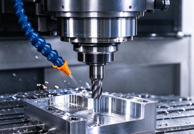
Accurate measurement of surface roughness is a core aspect of Quality Control (QC) and Final Quality Control (FQC). In CNC machining, measurement methods primarily fall into contact stylus profiling, non-contact optical scanning, and visual/tactile comparison methods.
1. Contact Stylus Profilometers — The Primary Industrial Choice
Contact profilometers are the most widely used quantitative inspection tools in quality control labs and machine shops.
Working Principle: Fitted with an extremely fine diamond tip (normally 2 µm or 5 µm radius of curvature). In operation, the drive mechanism slides the tip across the surface at a consistent speed. As the tip rises and falls across the micro-highs and lows on the surface, a transducer changes this mechanical motion into electrical signals which are analyzed by the system’s software for Ra, Rz, and Rt.
Applications: Regularly carried out for the great majority of turned, milled, and surface-ground components.
Key Measurement Protocols (To Avoid Errors):
Cut-off Length Selection (λc): Needs to be made considering the expected roughness value (generally accepted values for cut-offs are 0.8mm or 2.5mm); otherwise, the value of Ra could be incorrect.
Measurement Direction: The direction in which the stylus moves has to be at right angles to the direction of machining lay (grooves). For instance, in case of turned parts, the direction has to be axial and not circumferential.
2. Non-Contact Optical Profilometers — Ultra-Precision & Nondestructive Testing
For soft materials or ultra-precision parts, non-contact metrology eliminates the risk of scratching the workpiece surface due to the interaction between the stylus and the part.
Technology Types:
White Light Interferometry (WLI): This is a technology that relies on the process of interference of light waves for measuring minute high-resolution differences on a surface with a nanometer accuracy, hence making it ideal for ultra-precise components.
Laser Confocal Microscopy: Scans point-by-point via laser to reconstruct 3D surface topography, measuring not only Ra (line roughness) but also calculating Sa (areal roughness).
Applications: Mirror-polished parts, optical lenses, medical implants, extremely soft materials (e.g., pure aluminum, rubber/plastics), and complex 3D surfaces with microstructures.
Pros & Cons: Extremely fast and nondestructive, but equipment costs are high, and surfaces that are highly specular or transparent require special anti-reflective preparation.
3. Surface Roughness Comparison Standards — Shop-Floor Quick Audits
Working Principle: Standard calibrated metal plates having standard Ra values (such as 0.8 μm, 1.6 μm, 3.2 μm), manufactured through different machining operations (turning, end milling, face milling, grinding).
Operating Method: Scratching the surface of the workpiece as well as the standard plate using fingernail, while at the same time checking for gloss and tool marks through bright illumination.
Applications: Inspection of first article while machining and for shop floor troubleshooting.
Limitations: Semi-quantitative technique; highly dependent on operators’ experience; cannot be used as quantitative evidence in CMM inspection report.
Practical Tips when Measuring CNC Surface Roughness
Thoroughly Clean the Workpiece
Prior to performing the measurement, remove any residues of coolant, swarf, and oil marks from the workpiece with lint-free wipes and isopropyl alcohol (IPA). Even the slightest contamination can influence the results of the readings drastically.
Secure the Workpiece and Instrument
If contact measurements have to be made, it must be ensured that the piece and instrument base are firmly fastened to prevent any interference from outside.
Take Multi-Point Averages
The measurement should be taken at least three different points of the part (front, middle, rear). This is done to prevent defects of a specific point from influencing the whole evaluation process.
Calibrate Equipment Regularly
The tips of the stylus wear out with time. The profiler must always be calibrated before using it with high accuracy calibration blocks.
How to Improve and Optimize Surface Roughness in CNC Machining?
For improving the surface finish or lowering the Ra value in CNC machining, an approach involving both real time machining and post machining processes is needed. Tuning the process parameters along with post machining procedures helps to meet strict demands in the following situations:
Machining Process Optimization
Implement intervention accurately with parameters, equipment, and systems during the cutting process to avoid microscopic surface flaws on the part’s surface:
Optimizing Cutting Parameters: During fine machining process, it is best to reduce the feed rate to reduce the distance between tool marks in order to reduce scallop height. At the same time, increasing the spindle speed while decreasing depth of cut (Ap / Ae) will prevent BUE from forming.
Utilizing Wiper Inserts: For the process of turning or face milling, use inserts that have flat wiper flats or specific geometry. “The wiper inserts scrape flat” the micro-undulations created by the primary cutting edge, with the advantage of increased feed rates, thus efficiency in production and extremely low roughness.
Minimizing Tool Overhang: In order to fulfill the needs of machining depth while using the shortest overhang of the tool from the chuck or tool holder, the rigidity of the system should be high because the low system rigidity is not conducive to low roughness surfaces.
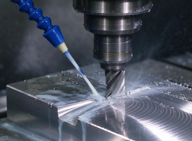
High-Pressure Cooling & Evacuation: The high pressure cooling or internal cooling system or directed cooling through jets to the cutting region should be used. This will reduce the heat generated during cutting so that the thermal distortion is avoided.
Combining Surface Post-Processing Operations
When dealing with ultra-precision optics, high-end medical devices, aerospace components, or cosmetic enclosures where mechanical cutting reaches its physical limit, post-processing operations must be leveraged to achieve the ultimate leap in surface finish:
Mechanical / Manual Polishing & Bead Blasting: For metals like aluminum, copper, and stainless steel, manual or automated polishing via buffing wheels, sandpaper, or polishing pastes completely removes micro-tool marks. Micro-glass bead blasting eliminates residual stress and imparts an even, delicate matte texture.
Anodizing / Hard Anodizing: Most commonly used on aluminum alloy parts (6061, 7075). Post-CNC machining anodization or hard-coat anodization is very useful for improving the wear-resistance, corrosion resistance and giving good feel & appearance through the micro-pore sealing action.
Electropolishing: Best suited for complicated inner cavities of precision parts made of stainless steel and titanium alloys. It utilizes the electro chemical principle and selectively removes the minute peaks of the surfaces to give extremely flat and reflective surfaces.
How to Choose a CNC Machining Supplier for Surface Finish Requirements?
However, in the case of custom part outsourcing, buyers and engineers tend to stress dimensional tolerances and ignore surface finish assessments. In case a manufacturer cannot control the process, the parts delivered may have tool marks that are too deep, roughness out of specifications or cosmetic defects.
The following are important considerations in choosing a CNC machining company:
1. Machine Tool Precision & Spindle Quality
Hard Power Assessment: The type of machines and spindles employed by the supplier determines the machining capabilities of the supplier. The best machining needs the most accurate machines, which includes high-speed and high-rigidity CNC milling machines, and CNC turning.
Maintenance of Equipment: Care of Machine Tools: Old and poorly maintained machine tools cause backlash and vibration which can never be eliminated on the machined surface.
2. Comprehensive Manufacturing & Post-Processing Options
One-Stop Service: The great suppliers not only possess the capability to cut but also have all capabilities to perform post process operations within or outside themselves.
Scope Coverage: It needs to be ensured that the supplier can provide solutions for roughing to finishing and other surface finishing (polishing, bead blast, anodizing, electroplating, passivation, or electroless nickel plating).Single source delivery is quite effective to avoid surface scratches and liability issues associated with multiple suppliers.
3. Advanced Inspection Equipment
Avoid “Visual Acceptance Only”: Ensure whether the vendor has professional measuring instruments in the QC department.
Checklist for Verification: Inquire about the availability of contact stylus profiler or 3D optical profiler at their end, and ensure that they can give Ra and Rz values in their Inspection/CMM Report as quality control parameters.
4. DFM (Design for Manufacturability) Engineering Support
Upfront Communication: A reliable supplier will not blindly start machining upon receiving 3D CAD files; instead, they will provide a thorough DFM evaluation.
Value Addition: Skilled engineers proactively identify excessively stringent surface roughness callouts on drawings (such as unnecessarily specifying Ra 0.8 deep inside internal cavities). By adjusting toolpaths or relaxing non-critical surface specs while preserving functionality, they significantly reduce your procurement costs.
Why Choose KENENG as Your CNC Surface Finish Partner?
In custom CNC machining, precise surface finishing is dependent upon advanced technology as well as process control skills. KENENG Hardware features a 3,000 m² facility equipped with 16 advanced CNC machines and 60+ expert technicians, providing one-stop solutions for surface finish needs.
Micron-Level Roughness Control & Ultra-Tight Tolerances
Roughness Capabilities: Surface roughness that can be achieved during machining includes standard roughness (Ra 3.2 micrometers), fine roughness (Ra 0.8 micrometers), and mirror finish (Ra 0.05 micrometers) besides polishing and grinding.
Precision Tolerances: By use of 3-axis, 4-axis, 5-axis CNC machines and mill-turn centers, the tolerance level that can be achieved is ±0.0127 mm (±0.0005”).
50+ Materials Processed with Proven Cutting Expertise
Extensive expertise in machining aluminum alloys (6061/7075), stainless steel (304/316), copper alloys, titanium alloys, and engineering plastics such as PEEK, POM, Nylon, and Acrylic—ensuring smooth, burr-free surfaces.
Complete One-Stop Surface Post-Processing (Finishing)
Provides bead blasting (matte), anodizing (Type II/III), electroless nickel/zinc plating, passivation, powder coating, and polishing services to deliver ready-to-use finished parts without multi-vendor handling risks.
Free DFM Evaluation & CMM Inspection Guarantee
Free DFM: Our engineers help you optimize your surface roughness requirements and process routing prior to machining in order to cut down on manufacturing costs.
Rigorous Quality Control: Fitted with CMM’s and profilometer equipment to guarantee that all delivered parts meet the drawing Ra/Rz requirements.
Flexible Low-Volume & Rapid Delivery
It supports single-piece prototype to low volume production at the fastest delivery of 3 business days, with 24/7 online support for your project to stay on track.

Conclusion
Achieving very smooth surface roughness usually requires lower feed rates, increased tool change frequency, and additional polishing stages, which considerably elevate the cost of manufacture. Hence, an ideal engineering approach involves setting up surface roughness tolerances that are necessary from the functional perspective of the parts.
If you are looking for a professional CNC machining team, feel free to contact KENENG!