
How CNC Part Geometry Affects Machining Cost and Production Time?
CNC machining is commonly used to make precision parts with careful dimensions, intricate forms, and repeatable results. However, the cost and production time of CNC machined parts are not determined by material selection and machining equipment alone. CNC Part geometry matters a lot for how the job goes.
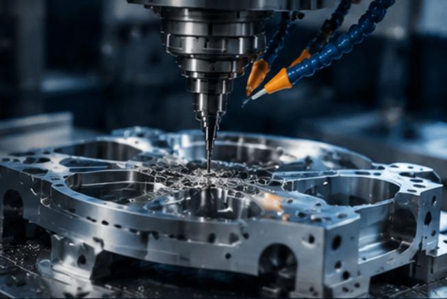
Geometric features such as part size, wall thickness, hole depth, corner radius, cavity design, and surface complexity directly influence machining operations, tool selection, setup requirements, and material removal time. When the design is simple, it is usually faster to make. When the design is hard, it can demand special cutters, extra setups, slower cutting, and more checks during production.
So, when designers, engineers and manufacturers understand how CNC part geometry affects machining cost and production time, they can adjust drawings early. That can lower avoidable spending and speed up output.
Table of Contents
Key CNC Part Geometry Factors Affect Machining Cost
1. Part Complexity and Machining Difficulty
Part complexity is a major geometric driver of CNC component cost. If a part has flat areas, straight edges, and basic holes, shops can often handle it with common milling or turning steps.
But when a part has tricky contours, rounded areas, uneven shapes, or several features that meet in tight ways, the shop usually needs more careful machining planning.
These kinds of shapes may also push the work toward multi-axis CNC systems. They can also require custom workholding and extra programming time. As a result, machine costs go up and the overall run takes longer.
For instance, a simple rectangular aluminum part might only need basic milling and drilling. By contrast, a part with curved surfaces, deep pockets, and angled areas may call for 5-axis machining plus multiple finishing steps.
Because of that, removing features that do not add real function is one practical way to cut manufacturing cost.
2. Wall Thickness and Structural Design
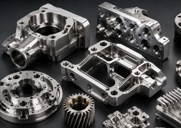
Wall thickness affects machining stability, cutting conditions, and cycle time.
Thin-walled parts tend to be harder to cut. They can shake during cutting, move slightly, and end up with dimension issues after material is removed. Cutting forces may bend thin sections or shift them, so it becomes harder to hold tight tolerances.
To manage this, manufacturers may lower the cutting speed, use smaller depth of cut values, add extra support during clamping, and run more finishing passes.
Thicker walls usually add stiffness. That can make the machining process steadier. Even so, walls that are thicker than needed cost more in raw material and increase material removal time.
Designers should weigh wall strength, required function, and the ease of machining when choosing wall thickness.
3. Deep Cavities and Pocket Geometry
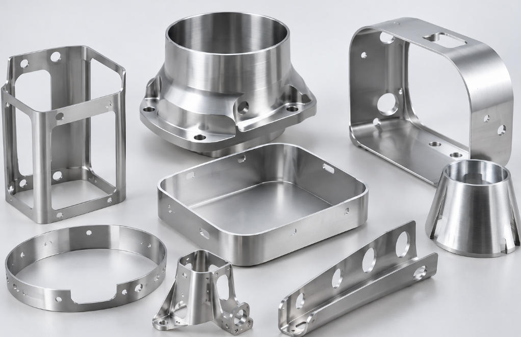
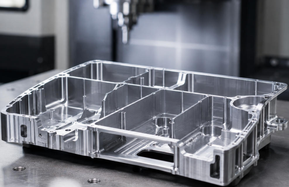
Deep cavities and pockets can raise CNC machining time and cost fast.
For deep pocket work, cutting tools must enter tight or recessed areas. Long-reach tools are often used. At the same time, they bend more easily and can chatter during cutting. That can lower accuracy and leave a poorer surface.
Deep cavities also make chip removal harder. Chips can block the cutting zone. Heat may not clear well either. Tool damage can follow. Surface finish can suffer. Work may need more stopping to recover.
In many cases, manufacturers rely on long-reach tools made for the job. They may lower cutting parameters. They often split work into several roughing steps and then finish passes.
If the part shape allows it, designers should skip pockets that are deeper than needed. Wider access helps too. Larger pocket corner radii and more open shapes can improve machining speed.
4. Hole Size, Depth, and Position
Hole design is another key cost driver for CNC machining.
Common holes with typical diameters are usually cheaper. This is because drill bits for those sizes are standard. Regular drilling methods can handle them.
Cost can rise with small-diameter holes, deep holes, angled holes, and high-accuracy holes. These need extra care in setup and tool choice.
Deep holes may call for peck drilling or other deep-hole CNC drilling methods. The goal is to clear chips and reduce heat. Small holes often need micro-drilling tools. Those tools run with tight control of cutting parameters.
Hole placement also affects the process. Holes on different faces may force extra repositioning. Some layouts can require multi-axis machining to reach each location.
Designers can cut production time by keeping hole diameters consistent. They can also avoid demanding precision where it is not required. Placing holes to limit setup changes can help as well.
5. Corner Radius and Internal Geometry
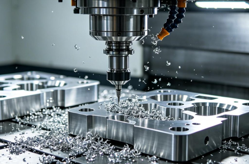
Internal corner radii influence tool choice and milling efficiency.
In CNC milling, many cutters are round, like cylindrical end mills. With normal milling, a perfectly sharp internal corner is not realistic. The corner radius comes from the tool diameter.
Very small internal radii require smaller cutting tools. These tools generally have lower rigidity and may need slower cutting speeds and smaller cutting depths.
As a result, machining small internal corners can require additional passes and increase the possibility of tool wear or breakage.
Using larger internal corner radii wherever functional requirements permit allows manufacturers to select larger, more rigid tools and complete machining operations more efficiently.
6. Undercuts and Difficult-to-Reach Features
Undercuts are geometric features that cannot be accessed using standard cutting tools from the primary machining direction.
Examples include T-slots, dovetail grooves, recessed channels, and internal locking features.
These geometries may require specialized tools, such as T-slot cutters, dovetail cutters, or custom-designed cutting tools. Some components may also require additional workpiece orientations or multi-axis machining.
Undercuts can increase programming complexity, machining time, and tool costs.
When designing CNC parts, engineers should evaluate whether undercuts are essential to the component’s functionality. Replacing unnecessary undercuts with accessible features can simplify manufacturing and reduce expenses.
7. Tolerances and Geometric Accuracy
Geometric tolerances determine how much dimensional variation is acceptable in a finished component.
Standard tolerances are generally easier and less expensive to achieve because they allow manufacturers to use conventional machining parameters and inspection methods.
Tight tolerances require greater process control, more accurate equipment, additional finishing operations, and more frequent measurements.
For example, a precision bore may require reaming or boring after the initial drilling operation. Components with demanding geometric tolerances may also require coordinate measuring machine (CMM) inspection.
The more stringent the tolerance requirements, the greater the possibility of additional machining time, inspection costs, and rejected parts.
Designers should specify tight tolerances only for features that directly affect assembly, performance, or safety.
8. Surface Geometry and Finishing Requirements
Surface geometry affects both machining strategy and finishing requirements.
Flat surfaces are generally straightforward to machine, while curved, contoured, and freeform surfaces often require more complicated toolpaths.
Complex surfaces may need ball-end milling, multi-axis machining, and multiple finishing passes to achieve the required surface quality.
Furthermore, certain geometric features may be difficult to polish, deburr, or inspect after machining. Internal channels and narrow cavities are particularly challenging.
A design that requires high-quality surface finishes across numerous complex surfaces will generally cost more than one with limited finishing requirements.
Designers should identify which surfaces require functional precision or specific surface finishes and avoid applying unnecessarily demanding finishing specifications to the entire component.
9. Part Size and Overall Dimensions
Part size influences material consumption, machine selection, workholding arrangements, and machining duration.
Large components require more raw material and may need larger CNC machines with greater working envelopes. They can also involve longer toolpaths and increased material removal.
Small components may require less material, but extremely small features can introduce challenges involving tool selection, workpiece positioning, and machining accuracy.
The overall geometry also determines how easily a component can be secured during machining. Irregularly shaped parts may require customized fixtures, increasing setup costs.
Optimizing the overall dimensions and simplifying the external shape can help manufacturers improve material utilization and reduce production expenses.
How to Optimize CNC Part Geometry for Lower Costs and Faster Production
Design for Manufacturability (DFM) is an important approach to improving CNC machining efficiency. It involves evaluating part geometry during the design stage to identify features that may increase machining difficulty or production expenses.
The following strategies can help engineers and manufacturers develop more cost-effective CNC components.
1. Simplify Unnecessary Geometric Features
Avoid adding decorative grooves, complicated contours, and unnecessary recesses that do not contribute to component functionality. Simpler geometries generally require fewer machining operations and less programming time.
2. Use Standard Tool-Compatible Dimensions
Design holes, slots, and internal radii around commonly available cutting tool dimensions. This reduces the need for specialized tooling and helps manufacturers use more efficient machining strategies.
3. Maintain Practical Wall Thickness
Avoid excessively thin walls and unsupported sections. Appropriate wall thickness improves structural stability during machining and reduces the risk of deformation.
4. Reduce Deep and Narrow Cavities
Whenever possible, use shallower pockets and wider internal channels. These features improve tool accessibility, chip evacuation, and machining stability
5. Minimize Workpiece Repositioning
Arrange geometric features so that more machining operations can be completed from the same orientation. Reducing repositioning can shorten setup time and improve dimensional consistency.
1. Apply Functional Tolerances
Specify tighter tolerances only where necessary. This prevents unnecessary precision machining, inspection, and finishing expenses.
2. Consider Material Removal Requirements
Avoid designs that require removing excessive amounts of material from solid stock. More efficient part shapes can reduce cutting time, tool wear, and raw material waste.
Common CNC Part Geometry Features and Their Cost Impacts
The following chart summarizes how different geometric features influence CNC machining costs and production time.
| CNC Part Geometry Feature | Machining Characteristics | Impact on Machining Cost | Impact on Production Time | Optimization Recommendations |
| Complex Contours | Requires complicated cutting paths and programming | High due to increased programming and machining expenses | Longer machining cycles | Simplify unnecessary contours |
| Thin Walls | Susceptible to vibration, bending, and deformation | Higher due to additional support and finishing requirements | Longer because of slower cutting speeds | Maintain sufficient wall thickness |
| Deep Pockets | Requires long-reach cutting tools and careful chip removal | Higher tooling and machining costs | Longer due to multiple cutting passes | Reduce pocket depth where possible |
| Small-Diameter Holes | Requires specialized drills and precise positioning | Higher when micro-drilling tools are needed | Longer due to slower drilling operations | Use standard hole diameters |
| Deep Holes | Difficult chip evacuation and heat management | Higher due to specialized drilling requirements | Longer because of peck drilling and tool changes | Optimize hole depth-to-diameter ratios |
| Small Internal Corner Radii | Requires smaller and less rigid cutting tools | Higher due to specialized tooling | Longer because of additional finishing passes | Increase internal corner radii |
| Undercuts | Requires specialized cutters or additional machining orientations | Higher due to tooling and setup costs | Longer because of additional operations | Avoid unnecessary undercuts |
| Tight Tolerances | Requires precision machining and additional inspection | Significantly higher when tolerances are unnecessarily strict | Longer due to finishing and measurement procedures | Apply functional tolerances only |
| Curved and Freeform Surfaces | Requires complex toolpaths and multi-axis machining | Higher due to advanced machining requirements | Longer because of detailed surface finishing | Simplify surface geometry |
| Large Part Dimensions | Requires more raw material and larger machining equipment | Higher material and machine operating costs | Longer due to increased material removal | Optimize overall part dimensions |
| Irregular Shapes | Difficult workholding and positioning | Higher due to customized fixtures | Longer because of additional setup operations | Design machining-friendly reference surfaces |
| Multiple Angled Features | Requires different tool orientations and repositioning | Higher due to additional setup and programming | Longer because of multiple machining operations | Align features to reduce repositioning |
| Narrow Slots and Channels | Requires small cutting tools and careful chip removal | Higher due to specialized tooling | Longer because of slower cutting speeds | Increase slot width where possible |
| Complex Surface Finishes | Requires additional finishing and polishing operations | Higher due to labor and processing expenses | Longer because of extra finishing stages | Specify surface finish according to functional needs |
| Excessive Material Removal | Requires extensive rough machining | Higher due to machine operation and tool wear | Longer because of increased cutting time | Optimize the part shape to reduce material waste |
The Relationship Between CNC Part Geometry and Production Time
CNC part geometry influences several stages of the CNC manufacturing process, not just the actual cutting operation.
| Part Geometry Feature | Manufacturing Process Affected | Influence on Production Time | Main Reasons for Time Increase | Optimization Strategies |
| Simple Geometric Shapes | Milling and turning | Short production time | Fewer machining operations and simpler toolpaths | Prefer straightforward geometric designs |
| Complex Contours | CAD/CAM programming and milling | Significantly longer | Complicated toolpaths and multiple cutting passes | Simplify unnecessary contours |
| Thin Walls | Roughing and finishing | Longer | Reduced cutting speeds and additional support requirements | Maintain sufficient wall thickness |
| Deep Cavities | Pocket milling | Longer | Long-reach tools, chip evacuation difficulties, and multiple passes | Reduce cavity depth and improve tool accessibility |
| Small-Diameter Holes | Drilling | Longer | Specialized drills and slower machining parameters | Use standard drill sizes |
| Deep Holes | Deep-hole drilling | Significantly longer | Peck drilling, chip removal, and tool repositioning | Optimize hole depth and diameter |
| Small Internal Corner Radii | Profile milling | Longer | Smaller tools require slower cutting and additional passes | Increase internal corner radii |
| Undercuts | Specialized milling | Longer | Special cutters and additional machining orientations | Eliminate unnecessary undercuts |
| Multiple Angled Features | Multi-axis machining | Longer | Additional positioning, setup, and toolpath programming | Arrange features to minimize repositioning |
| Curved and Freeform Surfaces | 3-axis and 5-axis milling | Significantly longer | Complex tool movement and surface finishing | Simplify curved surface transitions |
| Tight Tolerances | Precision machining and inspection | Longer | Additional finishing passes and dimensional measurements | Apply tighter tolerances only where necessary |
| Irregular Part Shapes | Workholding and machine setup | Longer | Custom fixtures and complicated positioning | Include accessible reference surfaces |
| Large Part Dimensions | Rough machining and material handling | Longer | Greater material removal and machine travel distances | Optimize overall dimensions |
| Narrow Slots and Channels | Slot milling | Longer | Small cutting tools and limited chip evacuation | Increase slot width where functional requirements allow |
| Complex Surface Finishes | Finishing and polishing | Longer | Additional machining and post-processing operations | Specify practical surface finish requirements |
Key Factors Determining CNC Production Time
| Production Time Factor | How Geometry Influences It | Potential Time-Saving Approach |
| Programming Time | Complex geometries require more CAM programming | Simplify designs and reuse standard machining strategies |
| Setup Time | Irregular shapes require customized fixtures | Standardize workpiece positioning |
| Cutting Time | Deep cavities and excessive material removal increase machining duration | Reduce unnecessary material removal |
| Tool Change Time | Multiple specialized features require different cutting tools | Standardize feature dimensions |
| Finishing Time | Complex surfaces and tight tolerances require additional passes | Simplify surface requirements |
| Inspection Time | Complex geometries require more measurement points | Simplify inspection-critical features |
| Rework Time | Difficult-to-machine features increase the risk of dimensional errors | Improve geometric design and machining accessibility |
CNC part geometry directly affects nearly every stage of CNC production time, from programming and setup to cutting, finishing, and inspection. Designing parts with simpler shapes, accessible features, practical tolerances, and standard dimensions can significantly reduce production time and improve overall manufacturing efficiency.
Summary
CNC part geometry affects both machining costs and production time. When a design includes thin walls, deep pockets, tiny holes, close inner corners, undercuts, tricky shapes, or hard-to-meet tolerances, the job gets harder. The shop may need extra steps and more careful machining.
Using design for manufacturability can help lower those issues. It lets teams remove features that do not add value, make sure tools can reach the surfaces, tune wall thickness, keep sizes consistent, and cut down on how many setups are needed.
Ultimately, effective geometric design is not simply about creating a component that meets functional requirements. It is also about making that component easier, faster, and more economical to manufacture while maintaining the required precision and quality. When product designers and CNC manufacturers talk early, the team often improves output speed and overall competitiveness.