CNC Machined Plastic Parts: Materials, Challenges and Best Practices
In modern manufacturing, CNC-machined plastic parts are widely used in industries such as automotive, medical, electronics, and industrial equipment. Compared to injection molding, CNC machining requires no tooling, enables rapid prototyping, low-volume production, and high-precision customization. As a result, it has become one of the preferred solutions for product R&D and small-to-medium batch production.
In this post, we will provide a systematic analysis of plastic CNC machining, covering process principles, material selection, application scenarios, manufacturing workflows, technical challenges, DFM optimization, and supplier selection, to help you make more efficient procurement and design decisions.
Table of Contents
Why Choose CNC Machining for Plastic Parts?
When faced with plastic engineering projects, many procurement professionals and engineers immediately think of injection molding or 3D printing. Why, then, does CNC machining remain an irreplaceable core process in today’s highly advanced digital manufacturing landscape?
No Tooling Costs:
Injection molds can cost up to tens of thousands of dollars to make, not forgetting that it takes long to develop them. CNC machining enables you to make cuts from sheets/rods, hence saving on research and development costs.
Low-Volume Production Flexibility:
For prototype development or low-volume orders ranging from dozens to hundreds of pieces, CNC machining offers an absolute advantage in both cost and lead time.
Superior Precision and Tolerance Control:
Although industrial 3D printing is developing rapidly, precision plastic CNC milling and turning still hold an insurmountable advantage in dimensional tolerances and surface finish.
Broader Material Selection:
Some special high-performance engineering plastics (PEEK and PTFE, for example) cannot be molded using additive manufacturing or injection molding processes without any errors. CNC machining will be able to work with pretty much all existing engineering plastics without affecting their natural qualities.
CNC Machining vs. Injection Molding: Which Process Suits Your Project?
When selecting a manufacturing process, evaluating production volume, cost, and lead time is critical to project success. Below is a direct comparison between CNC machining and injection molding:
| Dimension | CNC Plastic Machining | Injection Molding |
| Upfront Cost | Extremely low (only programming and material costs, no tooling fees) | High (requires an investment of thousands to tens of thousands of dollars for molds) |
| MOQ (Minimum Order Quantity) | Starting from 1 piece; highly friendly to prototypes and small-to-medium batches | Typically requires 1000+ pieces to amortize the tooling cost |
| Lead Time | Short (typically completed within 3–7 days) | Long (mold design and manufacturing takes 2–4+ weeks) |
| Design Flexibility | Extremely high (only requires modifying the 3D CAD model and CNC program) | Extremely difficult (once the mold is made, modifications are costly) |
| Part Complexity & Tolerance | Ideal for complex geometries; tolerances can reach±0.05 mm | Susceptible to shrinkage caused by uneven wall thickness; looser tolerances |
If you are in the product R&D stage, need quick design verification, or have an annual demand of under a few hundred pieces, CNC machining is the absolute premier choice. Injection molding’s cost advantage in mass production only becomes apparent when single-item demand reaches thousands or tens of thousands of units.
Common CNC Plastic Materials and Applications
In precision machining, choosing the appropriate material is considered half the battle. The molecular structure of various engineering plastics differs vastly, hence making their characteristics in terms of mechanical behavior, temperature limitations, and machinability very different.
The following is a detailed discussion of the five high-performance engineering plastics used in CNC machining:
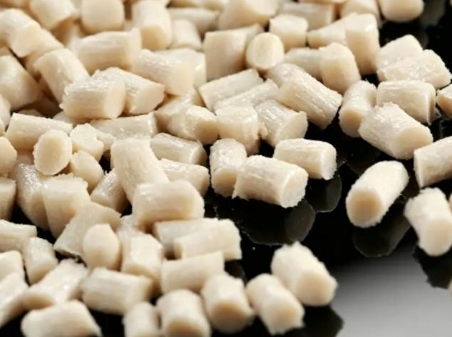
1. POM (Acetal / Delrin)
POM is a crystalline plastic known as “Plastic Steel.” High rigidity, high hardness, and excellent dimensional stability make POM easier to cut than any other engineering plastic. The working temperature range is 90-100°C, while the absorption of water is minimal (less than 0.2%), which makes POM able to withstand very precise tolerances even in humid conditions.
Burrs during cutting are rare, and the work result is excellent surface quality. In case of thin-wall sections, warping may appear due to the presence of residual stresses.
Typical Applications:
Industrial Machinery: High-load precision gears, cams, pump impellers, and conveyor drive sprockets.
Electronics: Precision insulating bushings, switch components, and wafer handling fixtures.
Automotive: Fuel system control valves and window lifter brackets.
2. PEEK (Polyetheretherketone)
PEEK is one of the semi-crystalline polymers found in the top league of specialty high performance engineering plastics. The polymer has been shown to perform consistently within extreme conditions of temperatures of up to 250 degrees centigrade while at the same time exhibiting high mechanical strength properties. This polymer cannot be dissolved by any chemical substance except 100% concentrated sulfuric acid.
It is highly resistant to abrasion, self-extinguishing (UL94 V-0 rating) and is proven to meet biocompatibility standards. PEEK being extremely hard and strong causes extensive tool wear when cut. This process involves the use of extra hard carbide and diamond coated PCD tools.
Typical Applications:
Medical Devices: Implantable bone substitutes, endoscope handles, dental surgical guides, and medical instruments requiring repeated autoclaving.
Semiconductor Manufacturing: Wafer carriers, CMP (Chemical Mechanical Planarization) retaining rings, and vacuum chucks.
Aerospace: Weather-resistant exterior connectors, high-performance fasteners, and pump/valve housings.
3. Nylon (PA6 / PA66)
Nylon (Polyamide) is renowned for its excellent impact toughness, low friction coefficient, high wear resistance, and great self-lubricating properties. However, Nylon is highly hygroscopic (moisture absorption). Upon absorbing water, its tensile strength decreases while its impact strength increases, and most importantly, its dimensions undergo slight expansion.
When performing multi-axis milling on Nylon, it is vital to understand the part’s actual working environment. If it operates underwater or in high-humidity environments, a tolerance allowance for moisture expansion must be factored into the initial drawing.
Typical Applications:
Heavy Machinery: Heavy-duty crane guide rails, wear pads, industrial drive rollers, and crane sheaves.
Conveyor Systems: Wear-resistant lead screws, chain guides, and machine tool protective sleeves.
Fluid Engineering: Enclosures and non-corrosive liquid pump bodies.
4. PTFE (Teflon)
PTFE has an outstanding operating temperature range of -200°C to +260°C. PTFE has the lowest coefficient of friction of all solid materials (non-stick property), as well as exceptional dielectric and chemical properties that prevent corrosion by powerful oxidants, bases, and acids.
PTFE has low hardness and is very soft; it shows the phenomenon of creep (ability to deform elastically under the effect of cutting loads). Consequently, machining PTFE requires extremely sharp specialty tools and strict clamping force control to prevent fixtures from leaving indentations on the part surface.
Typical Applications:
Chemical & Fluid Control: Highly corrosion-resistant flange gaskets, ball valve seats, chemical piping seals, and specialty laboratory vessels.
High-Frequency Electronics: High-frequency insulating terminals for 5G communication base stations, coaxial cable insulators, and RF connector insulators.
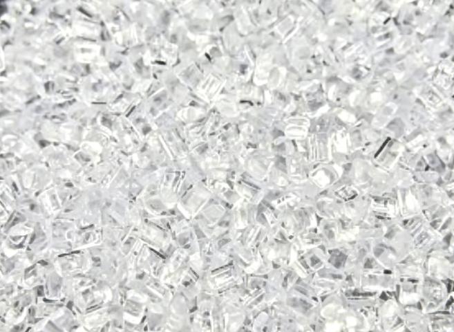
5. PC (Polycarbonate)
PC is an amorphous thermoplastic characterized by its astonishing impact strength (250 times that of ordinary glass) and a light transmittance of over 89%. It features excellent dimensional stability and superb rigidity at room temperature.
Although tough, PC scratches very easily and is highly sensitive to internal cutting stresses. If the toolpath programming is improper, accumulated cutting stress can cause fine surface cracks (crazing) to appear days after machining. Vapor polishing is typically required post-machining to restore its optical-grade, mirror-like total transparency.
Typical Applications:
Safety Protection: Industrial protective guards for automated equipment, explosion-proof sight glasses, and laboratory safety enclosure panels.
Instrumentation: Medical pressure gauge housings, lenses, optical sensor brackets, and LED light guides.
DFM (Design for Manufacturability) Tips for CNC Plastic Parts
Optimizing product geometry during the design stage not only significantly reduces manufacturing costs but also effectively prevents plastic deformation and burrs caused by cutting forces. Here are five critical DFM guidelines:
Avoid Excessively Thin Wall Thickness:
As compared to metals, plastics are much weaker. If thin walls are processed at high speeds using the machine, the walls get deflected because of the lateral force applied by the cutting tool, which gives rise to chatter marks or irregular wall thicknesses.
It is preferable that you have a minimum wall thickness of at least 1.5 mm. For hard plastic materials like PEEK, the minimum wall thickness can go down to 1.0 mm.
Use Radii and Corners Instead of Sharp Edges:
Because rotating CNC milling cutters naturally have a radius, they cannot directly cut absolute 90° internal sharp corners. Always design fillet transitions for all internal corners. It is recommended that the internal corner radius (R) be greater than or equal to the cutter radius (e.g., if using a Φ6 mm tool, the internal radius should be at least ±3.5 mm ; leaving a tiny clearance space drastically improves cutting efficiency and mitigates stress cracking risks).
Set Realistic Tolerance Ranges:
Tolerance limits for metals like ” ±0.01 mm ” cannot be used directly on plastics because of the easy expansion/contraction characteristics of plastics in response to changes in temperature and humidity levels. Tolerances can be increased to±0.1 mm to ±0.2 mm for mating dimensions that do not have any crucial importance. In case of precision fits, a tolerance limit of ±0.05 mm is more than enough for plastic precision tolerances.
Limit Deep Pockets and Deep Hole Structures:
In case of excessively deep pockets or holes, removal of chips is hampered and the result is a build-up of friction and thus the generation of heat that causes melting of plastic material and damage to slender cutting tools. During design, an aspect ratio of not more than 4:1 must be considered for holes/pockets.
Consider Tool Accessibility and Standardization:
In designing complicated shapes, make sure that the path for the CNC tool is unobstructed. Avoid undercuts at all costs because they normally need specially designed tooling which is quite expensive or machining processes where several axes have to move simultaneously. Furthermore, always make sure that hole sizes and slot dimensions are standardized throughout the whole drawing.
Challenges in Plastic CNC Machining
Plastic materials are extremely vulnerable to the effects of temperature changes, cutting forces, and internal stresses compared to metal. However, professional machine shops are known to solve these problems effectively via advanced technical approaches:
Technical Problem 1: Heat Induced Dimensional Changes
Problem Description: Due to their poor thermal conductive properties, plastic materials undergo dimensional changes due to high thermal expansion coefficients when compared with metals. Cutting operations can generate a great deal of heat and hence make plastics melt.
Solution Description: Employ sharp carbide and amorphous diamond inserts. In addition, increase the feed rate while reducing spindle speed. Finally, employ flood cooling with high-pressure soluble coolant.
Technical Challenge 2: Burrs and Residue
The Issue: Since plastic is elastic in nature, if the tool comes out of the part’s edge, instead of shearing, it bends. This results in burrs that are difficult to remove.
Factory Solution: Careful monitoring of the tool life and usage of new, sharp cutting tools. Efficient programming of tools during CAM (for example, using climb milling) and manual deburring/cryogenic deburring after machining.
Technical Challenge 3: Internal Stress Release Causes Plastic Parts to Warp
The Issue: Internal stresses build up in engineering plastics during their extrusion or compression molding process. After CNC machining where a considerable amount of material is removed, these internal stresses lead to deformation or even breaking of the part.
Factory Solution: Heat treat the sheets or rods before machining or employ a two-stage machining process, namely, “Rough Machining → Rest/Pause Secondary Annealing → Final Machining.”
Process of CNC Plastic Parts Machining
The process of making CNC machined plastic parts starts with a controlled procedure right from the CAD design review up to final shipment. Due to their sensitivity to temperature and stress compared to metals, the entire process needs proper planning and control for accuracy and consistency in quality.
CAD Design Review
Engineers evaluate the drawings either in 2D or 3D format prior to production to confirm that the designs are manufacturable and determine possible problems. These problems may involve the presence of thin walls, deep pockets, sharp internal corners, and feasibility of tolerances.
Solutions may be offered through design optimization. Examples include increasing wall thickness, corner radii, and ensuring proper fitments in assemblies.
Material Selection
Material selection depends on performance requirements such as strength, wear resistance, temperature resistance, and cost.
ABS is commonly used for housings and prototypes, POM for precision moving parts, Nylon for wear-resistant components, PTFE for chemical resistance, and PEEK for high-performance applications. The right material directly affects performance and machining difficulty.
Tool Path Programming (CAM)
Engineering professionals rely on CAM systems to generate programs for machining parts. Cutting parameters, including cutting tools, cutting speed, feeds, and machining paths, are chosen and optimized in order to increase efficiency, reduce material stresses, and minimize waste.
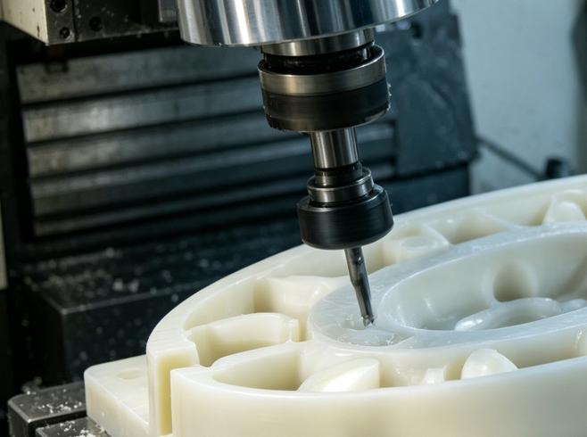
CNC Milling / Turning (Precision Machining)
This is the manufacturing stage where plastic raw material is machined into final parts. Milling is used for complex shapes, while turning is used for round components. Temperature control and vibration reduction are important to prevent deformation and ensure surface quality.
Surface Finishing
After machining, the components can undergo polishing, bead blasting, and deburring to enhance surface finish and aesthetics. Dyeing or coating of some components might be done to achieve desired outcomes.
CMM Measurement (Quality Control)
The completed components will be tested on CMM machines and basic gauges to ascertain accuracy of dimensions, tolerance levels, and other geometrical measurements. Components of high precision need to be fully measured.
Packaging & Delivery
After inspection, parts are securely packaged to prevent damage during transport. Orders are sorted and packed carefully, and export shipments may include inspection reports and required documentation.
Partner with a High-Quality Plastic CNC Machining Expert
Top-tier CNC machined plastic parts rely on advanced multi-axis precision machinery, strict raw material traceability, and a profound understanding of the physical and chemical behavior of various engineering plastics.
KENENG specializes in providing global clients with high-precision, custom plastic CNC milling and turning services. Whether you require medical-grade PEEK prototypes or high-volume POM precision gears, our engineering team will provide a free DFM analysis before manufacturing, ensuring your design transitions to reality seamlessly and at the most competitive cost.